 Image: Quality Digest
Correlation Between Contact and Non-Contact Surface Finish Measurement
Every industry
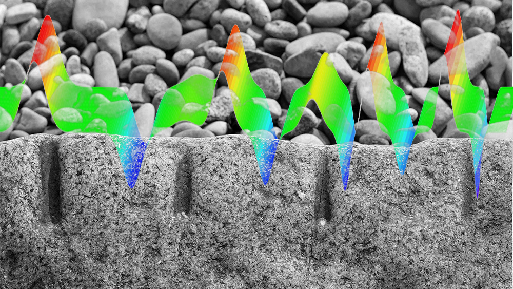
According to an article in Quality Digest, 2D contact stylus measurements and 3D optical confocal microscopy correlate well for surfaces with roughness between 0.1 µm and 10 µm. On blasted surfaces or finishes finer than 0.1 µm, optical light penetrates deeper into valleys than a mechanical stylus, yielding higher roughness values. The article notes that optical software can simulate stylus tip radius to align results between both inspection methods.
Sources: Quality Digest: Correlation Between Contact and Noncontact Surface-Analysis Equipment Is Critical
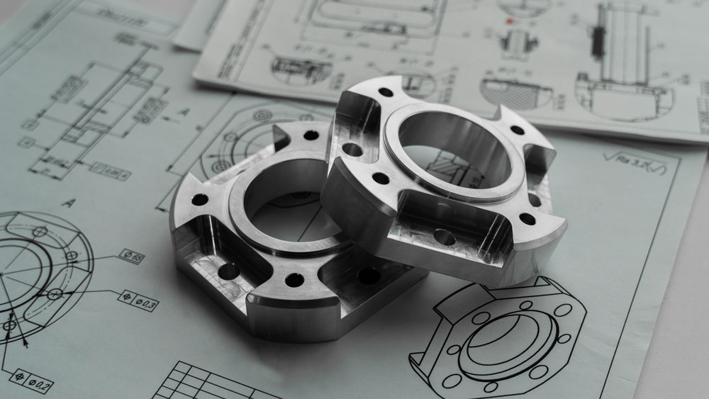 Image: Quality Digest
Controlling Drawing Revisions and Specifications in Inspection
Every industry
According to Quality Digest, quality issues often arise when inspectors and CMM programmers work from outdated technical drawings or STEP files. Document handoffs between design and the shop floor frequently fail during manual file exports, release updates, and feedback tracking. The article recommends establishing explicit release states, documented sign-offs, and generating inspection files directly from approved revisions.
Sources: Quality Digest: The Revision Gap
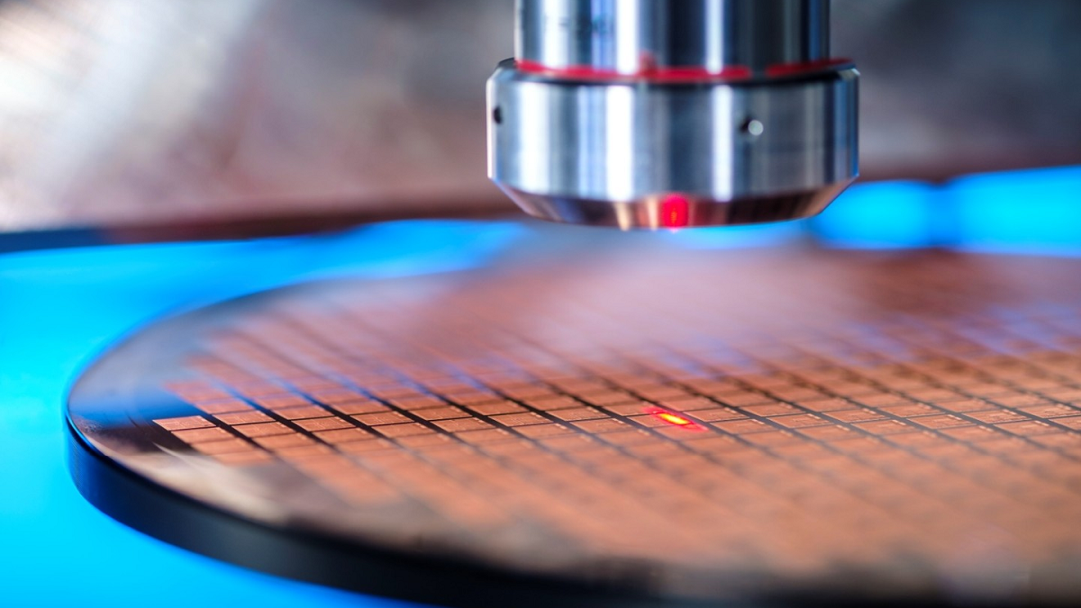 Image: Metrology News
Inline Optical Quality Assurance for Electronics Manufacturing
Electronics and appliances
According to Metrology News, Fraunhofer IPM has developed optical inline quality control systems for electronics manufacturing. The solutions include 3D digital holographic measurement for moving wafers and BGA structures without stopping production, UV fluorescence imaging to detect oil, grease, and flux residues on electrical contacts, and real-time plasma spectroscopy for laser-drilled microvias in multilayer PCBs.
Sources: Metrology News: Optical Inline Quality Assurance for Electronics Manufacturing
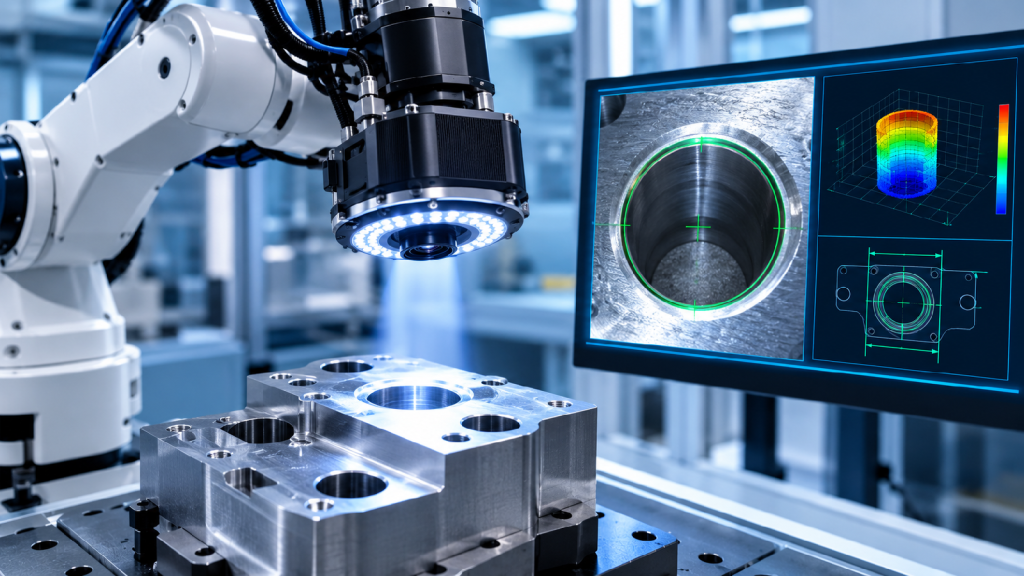 Image: Metrology News
Robotic Metrology for Blind-Hole Inspection in Machined Components
Auto parts and metalworking
According to research published in Frontiers in Artificial Intelligence and reported by Metrology News, an automated system combining a 6-axis robot, computer vision, and adaptive lighting measured blind-hole position and diameter. Testing on holes with diameters from 5 mm to 15 mm and depths from 10 mm to 45 mm yielded a mean 3D position error of 0.0322 mm and a mean diameter error of 0.0544 mm. The study highlights that approach angles of 15° or higher increase measurement errors.
Sources: Metrology News: AI-Assisted Robotic Metrology Targets Blind-Hole Measurement Challenges